Installation tips: Fluke describes testing tools used in the solar industry
Solar Power World has dedicated its March 2024 coverage to installation tips for solar contractors big and small. You can read the rest of our Q&As in the magazine and online here.
For insight into the “hand-held tools” segment,SPWtalked with Will White, solar applications specialist atFluke, to learn more about the various electrical testing tools used in the solar industry.
What PV testing tools are used during solar project construction and commissioning?
There aren’t a lot of tests that are done during construction. The big one is insulation resistance testing — ensuring that the insulation of the wiring hasn’t been compromised during the installation process. That’s best done after the wires have been installed, but before they’ve been terminated. For example, running from a combiner box to an inverter: They’ll run the wire through the conduit, but before they actually terminate at the combiner box, they’ll do an insulation resistance test to make sure the insulation hasn’t been damaged. And that’s also a good way to find ground faults before they become a problem. Voltage and polarity testing is another test that can be done during construction or is definitely done at commissioning. That’s looking to make sure they’ve got the correct number of modules in the series string — like making sure somebody didn’t accidentally plug in 12 instead of 10 panels. Polarity testing is used to ensure that they connected the positives to the positives and the negatives to the negatives, and there can be some pretty major consequences if those are wired incorrectly. A lot of times at commissioning, they’ll do IV curve tracing to ensure that the modules are working properly. They’ll do thermal imaging in a lot of cases, and to do thermal imaging, the system has to be operating.
Are these tests done in all solar markets?
In commercial, industrial and utility-scale, these tests are done in almost every case and are being done with consistency. At the residential scale, it depends. Those teams are really under pressure to get stuff done and get in and out super quickly, so they tend to be on the lighter end of the conditioning test scale. They’re not doing IV curve testing on residential unless it’s a serious troubleshooting problem. But voltage and polarity testing, they should be doing those. If you do a simple voltage polarity test in residential, it’s better than nothing.
Has increased voltages (1,500-V) changed devices?
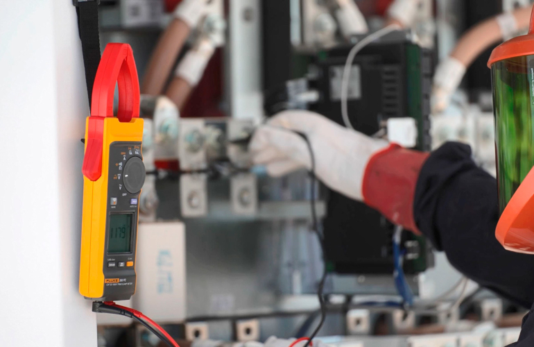
A CAT III 1,500-V clamp meter rated for the power of today’s PV systems is useful for measuring DC power, AC/DC voltage and current and for troubleshooting inverters.
Yes, and clamp meters are a really good example, because it’s really obvious. A clamp meter is used for testing current while the system is operating without having to actually touch the terminal. It’s a noncontact current measurement. We have a line of 25 or 30 different clamp meters, but there are ones that we specifically recommend for solar.
For residential systems, there’s a 325 clamp meter, that’s a 600-V reading meter. Residential rooftop systems are limited to 600 V or less by the National Electrical Code. The next step up is your non-residential buildings. Solar rooftop systems on commercial/industrial buildings are limited to 1,000 V, and we have a 370 series that are 1,000-V rated meters. Then when you get into the ground-mounted systems, you can go up to 1,500 V, and we have a 393 clamp meter that is 1,500-V rated.
As the voltage of the DC side of the system has progressively increased, we’ve had to develop new tools specifically to address those higher voltage situations.
What ratings or certifications should devices have?
There are standards and UL listings that are true of any type of electrical equipment. But there are standards for testing measurement equipment, which we follow, that have category voltage ratings based on the environment you’re using the tool in.
The solar array by an IEC standard is considered a Category III environment. When solar people are looking at test tools, they want to look at the Category III voltage rating of that tool. That covers the potential that a transient voltage spike is going to come from a power source like the utility. A transient voltage spike is a momentary, very high spike in voltage. If you happen to be on your meter on the electrical equipment when the transient voltage spike hits, that can overload the meter and damage it and potentially cause a safety hazard to the user. So that category rating says how close to the power source you are. Solar arrays are Category III environments. Things like electrical switchgears, utility meters and main service disconnects are Category IV and have a higher standard for that safety rating.
Category ratings are first, then the second is voltage rating of the tool. There are different voltage ratings, depending on which category rating. Our 393 clamp meter is a Category III/1,500-V rating. The 370 series is Category III/1,000-V rating.
For testing measurement tools, you should know the category environment you’re in and the voltage of the equipment. You want to make sure that the tool has a higher rating than whatever voltage you’re working on.
With so much monitoring in inverter apps and elsewhere, why are your devices still important?
Inverters are great for diagnosing certain issues. On the commissioning side, it’s important to do voltage and polarity testing before you turn the system on, especially on string inverters and central inverters. It’s important to do those tests before you turn the system on because you can identify problems before they become bigger problems.
The inverters that we’re using these days are transformerless, and they essentially do an insulation resistance test every morning before the system turns on. But again, when you’re doing the installation, you want to identify those problems before you turn the system on. When you get into the operations and maintenance and troubleshooting side, a lot of times the inverter can identify that there’s a problem there, but it’s not necessarily going to tell you what the exact problem is or where that problem is located. You’re going to use your test and measurement tools to dig in deeper to find the root cause. There are inverters that do IV curve traces internally and that’s starting to become a little bit more common, but having the individual IV curve tracer gives you the ability to go out into the field and really pinpoint problems.
On the residential scale, you likely have module-level monitoring, and the monitoring is going to tell you that this module is having the problem, but it doesn’t necessarily tell you what the problem is. Doing an IV curve test on that module will give you more detailed information, and it will give you the documentation that you’re going to need to do a warranty claim with the module manufacturer. Same thing, the inverter is going to tell you there’s a power quality issue, but it’s not going to tell you what it is or where it’s coming from. It’s just going to do emergency shut offs and say there’s an AC overvoltage. That’s great, but what’s causing that? Why did it happen? Power quality meters will give you that information and can do the logging.